By: Mark Mervine
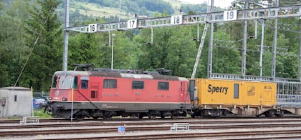
Märklin® has produced the Swiss Re4/4II in a number of variations over the years. I was fortunate enough to be able to pick up a couple of the 34XXX series Delta versions at a good price. These came with a circuit board with a built-in Delta decoder, Swiss directional lights, and a 3 pole AC motor. Although, they each ran well, I wanted to upgrade them to full digital for even better operating characteristics.
Recently, fellow chapter member Jeff Koellmer and I converted my Re4/4II, number 34341, to full digital by replacing some of the stock parts with new ones. This article describes which new parts were required and how we accomplished the installation.
In addition to the locomotive itself, the parts needed for the upgrade were as follows:
a) Märklin® #60760 digital upgrade kit
b) Lussi® #8016 Re4/4II Printed Circuit Board (PCB) which was equipped with a NMRA standard 8-pin plug.
c) Lokpilot® v3.0 Digital Decoder, ESU® part number 52610.
These parts were all obtained from Lussi®, Märklin® and ESU® dealers.
An ESU® Programmer device attached to a Personal Computer (PC) was used to adjust the decoder’s settings once the installation was completed, but this could also have been accomplished with other devices (Märklin® 6021 Control Unit or Uhlenbrock Intellibox). Other tools required for the installation were a soldering iron, wire cutter, needle nose pliers and small screwdriver. We found that it helped to have two people working to aide in the de-soldering/soldering process (extra set of hands).
Step 1 – Remove the Locomotive Body
The first step in the process was to remove the locomotive body. There is one retaining screw that is accessible when the locomotive is inverted and placed on a work surface. Access to the motor and electronics was available when the locomotive chassis was set upright again.
(Click Images to Enlarge)
In preparation for upgrading the motor, we carefully cut the power (black) and ground (brown) wires leading from the circuit board to the powered bogie (see below). We then removed the screws holding the bogie in place and it easily came away from the frame.
Next, we removed the motor shield and 3 pole rotor, then cleaned the rotor housing. Using motor parts from a Märklin® 60760 upgrade kit, the rotor, brushes, and shield were replaced. The original screws that attached the shield were re-used. The inductors from the kit were soldered to the motor shield and the motor leads re-attached. Note that if a 60760 kit is not available, the following individual parts can be used:
389000 field magnet
386940 motor shield
516520 inductor
601460 pair of brushes
Once the motor was re-assembled, we reinstalled the powered bogie back into the chassis.
Step 3 – Replace the existing PCB
The next step in the process was the most difficult, but was made easier with two sets of hands. First, we disconnected all of the wires going to the original Delta circuit board using a soldering iron and a small plier. The original circuit board was removed by backing out the two screws that hold it in place. The replacement board from Lussi® was then installed and temporarily held in place by one of the screws. The leads to the lights and the motor were soldered to the new board in their respective locations. The new Lussi® circuit board already had all of the resisters needed for the LED lights, so it was a one for one replacement with the original (see below).
Once the leads were in place, we loosened the circuit board enough to install the decoder. The new decoder was plugged in to the PCB’s socket, and we carefully coiled and secured the excess decoder wires using a small tie wrap. The screws that hold the circuit board were replaced and the physical portion of the conversion was complete.
Before continuing, we decided to perform a bench test. We placed the chassis with the new circuit board and LokPilot® decoder on a special programming track. We used the ESU® Programmer device (connected to a PC) to adjust a few key parameters and check that all was working as anticipated. The decoder parameters we changed were related to the locomotive’s address, acceleration and breaking delays and the four CV’s as recommended for a Märklin® 5 pole motor as follows:
CV2=3
CV53=40
CV54=20
CV55=38
Step 4 – Final Test
All that was left to do then was to re-install the body on the chassis, place the locomotive on our layout and dispatch our creation while enjoying the smooth operation of the 5 pole motor and LokPilot® combination. The Lussi® circuit board provided full digital control of the Swiss lighting using F0. With the original Delta circuit board, the lights only worked when the locomotive was physically moving. Overall, we found the process to be straight-forward, quick and well worth the effort and added expense.


